Stability through Time Variation: Ursa Major Space Station

In 1978, Christopher Moore’s company, Ursa Major, released the Ursa Major Space Station:

The Space Station, or SST-282, was described as a “reverberation effect.” It could apparently get reverb times of up to 3.5 seconds. This may not seem like a particularly long time by modern standards, but it was a huge achievement given the architecture that was used. In the SST-282, the reverb effect was obtained by using a single delay line, with 15 output taps from the delay buffer summed and used for feedback, and an additional 8 taps used to monitor the delay line. Multitap delay lines such as this, where several taps are summed and used for feedback, can quickly reach a high reflection density. However, they are notoriously unstable, with the maximum feedback gain being allowed under conventional circumstances being equal to 1 divided by the number out output taps. Yet Moore was able to achieve a significantly higher feedback gain. How?

Fortunately for geeks like myself, Moore extensively documented the process he used (which puts him in my DSP Hero list). The basic diagram of the algorithm is right there on the front panel, and Moore also described the algorithm in a patent. The key diagram from the patent:
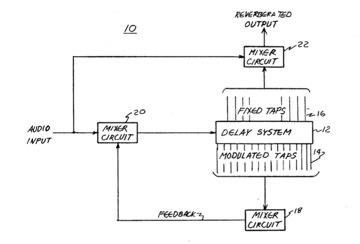
The basic idea is that the taps that are summed and used for feedback are modulated. In the patent, Moore describes the clever modulation process used, as well as the tap spacings. By moving the feedback taps back and forth, Moore was able to get a much higher feedback gain before instability, which results in a longer decay time.

I built my own version of the SST-282 back in 2001 or so, using a program called SynthBuilder. I found that by modulating the taps as Moore describes in his patent, I was able to get about a 3X increase in feedback gain before things started getting too weird. Mind you, they got pretty weird anyway. The SST-282 simulation could get a reverb sound, but it sounded like it was full of spooky voices at high feedback settings. Very cool stuff.

Christopher Moore used a similar topology for the later Stargate reverb, but with a longer delay buffer. By doubling the delay buffer size, the maximum reverb time before instability is also doubled. Apparently the Stargate used a somewhat different randomization scheme as well – see below.

Moore has recently described some of the issues that the original SST-282 had:

…I had not been able to tame the various flaws I could hear in the Space Station. These included spectral smearing (due to the wandering feedback taps), modulation noise (delay taps were simply picked up and moved 62uS with no smoothing), and the inability to get a really distant sound due to the fact that the Audition Delay taps by design picked up the dry source as early reflections as well as the dense later reverberation.

Later Christopher Moore designs, such as the 8×32 Reverb, the AKG ADR-68K, and a number of algorithms designed for Kurzweil, made use of stable reverberation algorithms. However, the Space Station’s method of obtaining stability through time variation resulted in a distinctive sound that is still useful to this day. The original Space Station algorithm was turned into the SST-206, a compact hardware version of the SST-282, and Eventide has released a plugin that uses the SST algorithm.

UPDATE: Chris Moore, in a comment on this post, points out that the randomization scheme used in the Stargate was considerably different than the Space Station:

You are right about the 323 as far as you go. The StarGate has a wonderful sound (thanks go to Charles Andersion for great support during the long and arduous tuning process), due to the invention of a different way to change delays. Without giving away the store (because I may revisit the design one day and have some really cool ideas to tame those moving delays altogether). Anyway, the 323 has no pitch smearing, no Doppler shift, and almost no modulation noise. No free lunch: it has a tremolo sound.

I had always thought that the Stargate was similar to the Space Station, except for a larger amount of memory used – I stand corrected.

Feedback, anti-feedback, and complexity in time-varying systems

“For my birthday I got a humidifier and a dehumidifier. I put them in the same room and let them fight it out.” – Stephen Wright

When I was researching the Eventide H910 Harmonizer, I found it curious that the box had controls for both feedback and something called “anti-feedback.” The service manual explains the anti-feedback control as follows:

Increasing clockwise rotation of the ANTI-FEEDBACK control progressively adds a small up and down frequency shift to the output signal, which serves to decrease the effect of room resonance peaks on the signal which ultimately re-arrives at the microphone.

In modern terms, I would call this a chorus effect, with a triangle wave modulator. Pretty simple. However, it is interesting to see how such a simple process can have a significant effect in a PA system – by turning on the Anti-Feedback control, you can increase the gain of a microphone being fed into the H910.

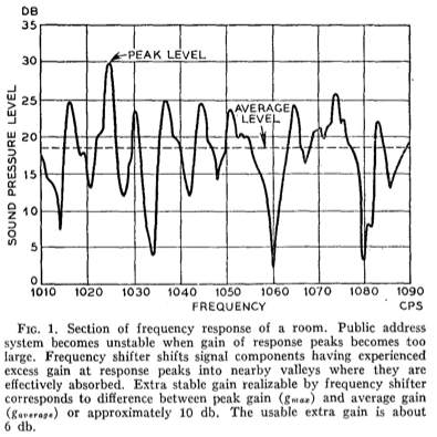
The idea of using a time-varying system, such as pitch shifting, delay modulation, or frequency shifting, to increase the maximum gain of a system before oscillation occurs, dates back many decades. In 1962, Manfred Schroeder (of digital reverb fame) published an article in the AES Journal about using frequency shifting as a method of increasing the gain of a PA system by up to 6 dB. A picture tells a thousand words, especially if it has a bunch of words attached to it:

Schroeder also discusses what happens if the gain is turned up beyond the feedback suppression limits of the frequency shifter:

For example, when using the frequency shifter, an excessive gain announces itself by a faint but easily recognizable “growl” or “chirp.” When this sound is heard, the operator decreases the gain by one or two decibels and the system continues to operate without the audience having heard any adverse effect.

This works well for gain increases up to a certain limit, but what happens when the gain is increased well beyond that point? The answer can be found in ValhallaFreqEcho. As the feedback gain is pushed beyond a certain level, the plugin will enter into a self-oscillating region, but one that has a huge amount of complexity. By controlling the shift frequency, delay, tone controls, and feedback gain, a variety of constantly evolving patterns can be produced. The overt goal of ValhallaFreqEcho is to get those chirps and growls that Schroeder described.

The Eno/Lanois “shimmer” sound works along similar principles. Pitch shifting, in and of itself, is a useful way of avoiding oscillation, as it pushes the feedback energy into regions that are above or below the original energy in frequency. However, if you turn the feedback gain up high enough, the system will start to self-oscillate, but in a highly chaotic manner. Keeping the gain just below self-oscillation will result in a sound that slowly evolves into a huge orchestral wash, that fades away into tinkling high octaves.

From a DSP developer’s perspective, delay modulation, frequency shifting, and pitch shifting all fall under the category of time-varying systems. Conventional digital signal processing theory concerns itself with linear, time-invariant (LTI) systems. Once time-variation is introduced, conventional LTI theory falls apart. There has been some research performed on what time-variation will do in otherwise linear systems, but there is no simple answer.

In some systems, time variation will make a simple system become unstable, such that its output amplitude grows out of bounds. Reverb developers call that “blowing up,” as that is the best way to describe the sound that comes out of the speakers. However, in the systems described above, time-variation serves to make a system more stable, in that it allows for the feedback gain to be increased. The onset of oscillation in such systems is something that is usually avoided in academic DSP, but in musical audio it is an area rich for exploration.

In my next post, I will look at an early digital reverb in which the entire theory of operation was based upon the increased gain obtainable through time-variation.

Shimmer: Modulation, auto-correlation, and decorrelation

In my previous post, I discussed the Eno/Lanois shimmer sound, and how it is based around a pitch shifter and a digital reverb placed in a global feedback loop. It is worth exploring what is going on in this signal chain at the micro level, and how a fairly simple signal routing can create such a complex sound.

The AMS pitch shifter used by Eno and Lanois used a de-glitching board in its architecture, to find the ideal points for splicing together the time-scaled waveform chunks. This presumably worked in a similar manner to the H949 de-glitching card, in that autocorrelation was used to find the most similar segments of the waveform, and the delay time of one of the channels was adjusted for an ideal splice. It is also possible that the auto-correlation would trigger a new splice, such that the rate between splices was a function of the periodicity of the input signal.

Auto-correlation works well for determining splicing points, assuming that the input signal has a certain degree of correlation. A single sustained guitar note, for example, can have a high auto-correlation factor after the initial attack. But what happens when the signal to be shifted has a very low auto-correlation factor? Such a signal is said to be decorrelated; that is, the auto-correlation or cross-correlation is said to be greatly reduced compared to the original signal.

In the audio world, decorrelation often refers to randomization of the phases of the signal while preserving the frequencies, or to a time-varying process to slightly shift the frequencies of a signal to prevent feedback. Both of these processes are present, to a large extent, within time varying reverbs such as the Lexicon 224 and EMT250 used by Eno and Lanois.

The Lexicon 224 Concert Hall algorithm is made up of a number of allpass delays, which preserve the input frequencies while completely scrambling the phase response. In addition, the Concert Hall algorithm uses time varying delays inside of the recursive delay network, which increased the perceived modal density of the reverb, and also impart a beautiful chorusing to the reverb decay. This lushness from time-varying delay lines is very prominent in 1980’s Eno/Lanois productions – in addition to the Concert Hall algorithm and EMT250, they made use of the multi-voice chorus algorithms in the Lexicon units, as well as the Symphonic preset in the Yamaha SPX-90.

So, what happens when a pitch shifter that uses auto-correlation to find the ideal splicing points is put into a feedback loop with a reverb that is highly decorrelated and time-varying? The answer: chaos. The pitch shifter will NOT be able to find ideal splicing points, as the phase of the reverb output is continually being scrambled.

The pitch shifter HAS to splice, whether or not it is a perfect situation, so it will pick the best possible match, but this will probably be a fairly random location each time. The result will be random delays for each new splicing point, or random sizing of the grain windows, depending on how the auto-correlation is used within the pitch shifter. This randomization will cause the sidebands of the input signal to be spread out, such that an individual sinusoid would be turned into a band of frequencies centered around the original (that has been shifted up by an octave).

Add in the additional octaves produced by the feedback, the random sideband spread caused by the modulation within the reverb, and harmonics that are created by analog nonlinearities in the feedback path, and the result is a HUGE amount of sonic complexity generated from a simple system. Put a sine wave into this type of feedback system, and the output can approach near orchestral levels of thickness.

In this light, it is interesting to think about Eno’s use of the DX7 around this time. The DX7 can produce chaotic sounds through the use of cascaded FM, but it can also produce gentle, minimalist textures through the use of parallel operators (sine oscillators). A simple DX7 patch with several parallel sine oscillators and a low FM index may produce a fairly boring sound on its own, but would create an enormous yet controllable sound when fed into a complex feedback loop of digital processing.

Coming up: more on the topic of generating complexity through simple systems with feedback applied to them, both from a technical and creative perspective.

Eno/Lanois Shimmer Sound: How it is made

The basic foundation of the Brian Eno / Daniel Lanois shimmer sound is fairly simple: Create a feedback loop, incorporating a pitch shifter set to +1 octave, and a reverb with a fairly long decay time. By controlling the gain and equalization of the feedback loop, and the lengths of the various delays within the loop, the temporal evolution of the sound can be altered from steel drum-esque sounds to the slow attack “string pads” hear on many of the Eno/Lanois tracks. This is the same technique used by ValhallaShimmer, with the reverberation, pitch shifting and feedback all incorporated within the same plugin.

Kevin Killen, answering a question about the signal flow on the U2 song “4th of July” on Gearslutz, described the signal path as follows:

The delay and modulation was derived from the AMS 1580. On its fader return , some hi frequencies were rolled off, then it was fed into a 224 Hall setting, probably 5 seconds but with a rolloff in the top and bottom. This return may have been equalised also. We may have added a second delay but then the delays have to be timed to the track as the net effect is blurring the chord progression…Our last tweak would be to play with the sends on all of the returns to the point that its almost recirculating out of control, which in turn is creating a layer upon layer effect.

The AMS DMX 15-80s was a digital delay / sampler / pitch shifter that was in common use in Britain in the early 1980’s. Eno and Lanois have both sung the praises of this unit, and Wendy Carlos has said that the AMS unit had “perhaps the least audible artifacts to pitch shifting available at that time.”

David Kulka has written that the AMS DMX had an optional de-glitch card installed, which worked on a similar principle to the auto-correlation deglitcher in the H949. His post is worth quoting:

Harmonizers, at least the early ones, had to electronically “splice” sections of the waveform in order to accomplish pitch change. When the out and in points had different voltage levels, a small DC pop could be heard at each transition. The result was a sort of low level crackle, more obvious with certain kinds of program material, and more audible at extreme pitch change settings.

The Eventide H910 exhibited this, along with the early AMS Harmonizers. Both Eventide (on the H949) and AMS partially resolved this by adding “de-glitch” cards. The circuitry on this card added a “smart” algorithm to pitch change, adjusting the transitions to better match voltages at the in and out points.

The “224 Hall setting” that Killen refers to is the Concert Hall algorithm in the Lexicon 224. This algorithm has a fairly low initial echo density, that builds to a higher density as the decay evolves. The Concert Hall algorithm is also distinguished by its high degree of modulation. The resulting sound is not a terribly accurate simulation of a real concert hall, but rather a lush and spatially expansive reverb that is still sought after more than 30 years after its introduction.

Other accounts of the “shimmer” sound refer to different reverbs being used, such as the EMT250. In addition, modulated delay lines, such as the Lexicon Prime Time, have been used by Lanois at different times. The common elements always seem to be the pitch shifter, a modulated reverb and/or a modulated delay line, and feedback and equalization generated via an analog mixer. In my next post, I will analyze the contributions of these elements to the shimmer sound, and will discuss how the various components respond in a feedback situation.

Eno/Lanois Shimmer effect: Early examples

The collaboration of U2 with Brian Eno and David Lanois was the first introduction to a wide listening audience of the reverb with swelling octave overtones that has come to be referred to as “shimmer.” However, the effect was in use by Eno and Lanois for some time before it was featured on the 1984 album, “The Unforgettable Fire.”

My favorite example of the sound comes from the 1983 album, “Apollo: Atmospheres and Soundtracks” by Brian Eno, his brother Roger, and Daniel Lanois. It makes up the huge background pad in the song “Deep Blue Day:”

Similar octave-shifted reverb sounds can be heard all over the album. Not all of the songs use the feedback configuration of the reverb feeding into a pitch shifter and back into the reverb. In “An Ending (Ascent),” the main melody instrument has a delayed pitch shifted signal an octave above and below, but no feedback:

A more “shimmery” sound (i.e. more feedback) can be heard in the “Prophecy Theme” from the Dune soundtrack:

In the next post, we will examine the signal chain used to get these sounds.

Pitch Shifting: The H949, and “de-glitching”

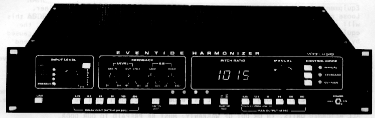
In 1977, Eventide released the H949 Harmonizer:

The H949 built upon the harmonizing features of the H910, and added more memory (for longer delays), randomized delay, reversed delays, flanging, and a micropitch mode for small pitch shift intervals. However, from a DSP developer’s perspective, the most interesting feature was a new circuit board, the LU618 or “ALG-3” board, that was an option for earlier H949s and was added as a standard mode to later units.

A somewhat technical review of the situation:

  • In the H910 and H949 pitch shift modes, information is being read into delay memory, and being read out at faster or slower rates, to change the pitch of the signal. Reading out of a delay line at a different rate than the data is written will quickly create a situation where the delay line runs out of samples to read.
  • In a modern delay line based around a circular buffer, if the read tap is moving through the buffer at a different rate than the write pointer, it will soon run into the write pointer, either by catching up to it or by being overtaken by it. Resetting the read tap to a different point avoids the issue of running out of memory or running into the write pointer, but this causes an audible popping sound as the read tap jumps instantaneously to some random point in the delay.
  • Pitch shifters deal with this artifact by fading the value of the read tap down to zero before making this jump, and then fading the volume back up again after the jump. In a 2-tap pitch shifter like the H910 and H949, the volume change can be viewed as a crossfade between the 2 read taps. This is directly analogous to what happens in the rotary head tape pitch shifters, as a given read head rotates away from the tape.
  • However, this crossfading is not without its problems. If the crossfading happens over too long of a time, the result is a metallic coloration of the sound, as the 2 read taps have a constant relative distance from each other that results in comb filtering. Having the crossfading take place over a shorter interval helps to reduce the comb filtering, but results in an audible “glitch,” as the phase differences between the 2 read taps causes cancellations in the frequency response that is heard as a volume drop during the crossfading period. This can be heard as a “stuttering” artifact in the pitch shifted sound.

The LU618 / ALG-3 board on the H949 works on eliminating this “glitch” artifact through a clever trick called autocorrelation. As described in an Eventide patent by Anthony Agnello, the ALG-3 board looks at the 2 delayed signals, and compares them to see where they share the most similarities – not just zero crossings, but true phase similarities. The H949 then calculates a delay offset, such that the new segment that is to be faded in is in phase alignment (or as close to phase alignment as possible) with the segment that is being faded out during the crossfade time. If the ALG-3 has calculated the delay offset correctly, the 2 segments that are being crossfaded between will be almost identical, which will result in the least cancellations in the frequency and amplitude response. Voila, glitch-free pitch shifting!

If only it were so easy. The H949 “de-glitcher,” and the de-glitching mode used in most time-domain pitch shifters that followed the H949, work well with signals that are as close to periodic as possible – i.e. a single monophonic musical line. Periodic signals have a high degree of autocorrelation, so the de-glitching hardware can usually find excellent splicing points. Voice can be de-glitched fairly, as can a monophonic guitar line. Once polyphonic signals (i.e. chords) enter the picture, it becomes harder and harder to find similar points to splice together. Noisy signals, like drums, will have almost no similar splice points (i.e. a very low autocorrelation value). In such a case, the de-glitcher will find the most similar points to splice together, but there is no guarantee that they will be in any way similar, so the result is more likely to have amplitude glitches.

Next week, we will discuss the various pitch shifting schemes and how they relate to the generation of the Eno/Lanois “shimmer” sound.

Early pitch shifting: The Eventide H910 Harmonizer

In 1975, Eventide came out with their first Harmonizer, the H910:

Designed by Anthony Agnello (later of Princeton Digital), this was a digital variant of the rotary tape head pitch shifters that I discussed earlier. Like the Lexicon Varispeech that preceded it, the H910 would be what I would label a 2-tap pitch shifter, in that there were 2 pitch shifted signals, with crossfading between the 2 signals. The H910 appears to use a fairly simple triangle wave crossfading, which means that the 2 different delayed signals will be present to a greater or lesser extent in the output at virtually all times.

So, why did the H910 become identified with pitch shifting, and the term “Harmonizer” become almost as generic as “Xerox” (at least in recording circles), while the Lexicon Varispeech faded into relative obscurity? I don’t know. If I had to guess, it has something to do with marketing. The Varispeech was described in the literature as a way of time correcting speech, while the Harmonizer was sold from the get-go as something to generate musical harmonies. Let’s face it, Harmonizer is a great name.

Whatever the reason, the Harmonizer quickly made its way into recording studios around the world. Tony Visconti famously described the H910 to David Bowie and Brian Eno: “It fucks with the fabric of time!” Visconti used the H910 while recording Bowie’s “Low,” where it was used to create a snare drum sound that descended downwards, with the amount of pitch bend determined by how hard Dennis Davis hit the snare:

The snare sound also has some sort of gating on it, but you can clearly hear the Harmonizer on the first snare hits. The H910 was set to a downshift setting of around -1 semitone, and the feedback was turned up to get the quick delays that shoot down in pitch.

One of my personal favorite examples of harmonizer (ab)use is “Duck Stab” by The Residents. Practically every song on this record uses harmonizer feedback, either for generating a detuned chorus on the vocal, or a minor third transposition with feedback to create “dimished” harmonies. Enjoy the following super creepy video while listening to the nifty pitch shifting tricks.

The first digital pitch shifter: Lexicon Varispeech

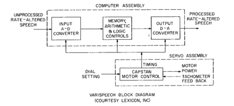
When I was planning my “editorial calendar” for the next few weeks, I had planned on discussing the Eventide H910 Harmonizer as the “first digital pitch shifter.” I even described the H910 as such in an earlier blog post. However, it turns out I was wrong. The Lee article that I discussed in my previous post describes what is probably the first commercially available pitch shifter, the Lexicon Varispeech:

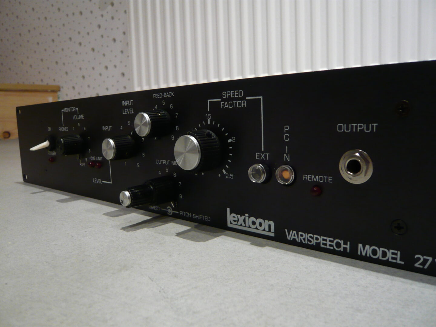
The Lexicon Varispeech was introduced in 1972, a good 3 years before the H910.  The Lexicon Pro website makes only passing mention of the device, describing it as a “Lexicon product for the language instruction market.” Fortunately, the Obsoletetechnology blog has a nice overview of the device, including photos, gutshots, and sound examples. The following image is taken directly from the aforementioned blog post, which you really should read:

Interestingly enough, for a device that was marketed as being used for speech and time compression, the Varispeech 27Y has a feedback knob. This is solely for use as a special effect, and was prominently featured on the H910 and H949 harmonizers of later years. I am uncertain if this was in the 1972 Varispeech, or if the 27Y was the original Lexicon model or a later version. If anyone has any info, please contact me.

Chris Walla of Death Cab for Cutie describes his use of the Lexicon Varispeech in an EQ Mag interview, where he also notes the incongruity of the feedback knob on a device used for time compression and expansion:

There was a lot of speech pathology research developed at Lexicon that was cross-purposed into pro audio. The Varispeech was originally intended to help stroke victims and people with speech disorders. The idea was that you could slow down a conversation at regular pitch but keep pitch where it was so that people could practice figuring out how to reconnect their mouth and their brain.

There was this weird period where [Lexicon was] screwing around with it; I got one that had a feedback knob, which as far as I can tell is completely useless for speech pathology, but it makes everything sound like Doctor Who, which is awesome.

It sounds great under the snare drum, and Tegan’s vocals run through it on ‘The Cure’ when she does the ‘Oh, uh oh, uh oh’ thing. The Varispeech is a really cool chorus-y, flange-y thing if you set it up that way. But it’s a speaker destroyer, too. It’s an old [’70s] effect, and Lexicon wasn’t worried about being sued by guys who were like, ‘You blew up my guitar amp, dude!’

Digital Pitch Shifting: Early work

One of the first discussions of time-domain digital pitch shifting can be found in a paper from a 1972 Audio Engineering Society convention:

Time Compression and Expansion of Speech by the Sampling Method

In this article, Francis F. Lee describes using digital storage to perform the same pitch shifting and time compression techniques that the older rotary tape head devices were used for. A fair chunk of the article is dedicated to the relative virtues of the bucket brigade technique versus random access memory, but I just skimmed over that, as neither of the techniques described apply to modern digital systems. The older digital boxes would change the actual output sampling rate in order to perform pitch shifting, as opposed to the interpolated reads at a fixed sampling rate that modern digital systems use.

An interesting part of the article is when Lee describes the artifacts caused by splicing together the shifted chunks of audio. If the chunks are simply switched in between, the result is very obvious “clicks” in the sound. From the perspective of a DSP developer 38 years later, I would compare this to using a single sawtooth oscillator to modulate a delay line. This results in a pitch shifted signal, but with some nasty clicks at the frequency of the sawtooth, as the delay length abruptly changes when the sawtooth resets.

Lee explains how the older rotary tape head devices could be adjusted to reduce such artifacts:

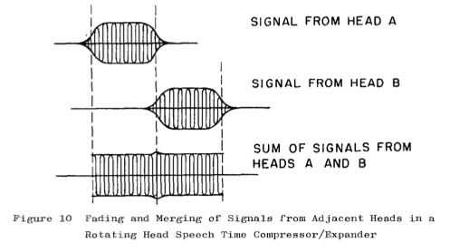
With the rotating head machines, by making the tape wrap-angle slightly more than the nominal 90 degrees, it is possible to have signals picked-up by adjacent heads to have a degree of overlap. Furthermore, as the tape and head come into contact or separate, the picked-up signal does not come up or drop off abruptly. The no-signal or signal to no-signal transitions are faded in and out, although rapidly.

An excellent illustration of this idea is included:

This is in sync with a process Wendy Carlos describes in her blog post on the Eltro Information Rate Changer, for adjusting the tape guides on the rotary head apparatus:

[The tape guides]were drilled off-centered to their support screws. So you could loosen the guides with an Allen’s wrench, and swivel them slightly. That way the nominal 90 degree angle the tape wrapped around the head drum could be increased or decreased, for best sounding results. A greater angle gave more of an overlap as one gap pulled away and the next one came in contact, and vice versa. You eventually learned where the optimum settings were for different material: speech, music, sound effects.

As we will see, the efforts taken to adjust the overlap between segments and minimize the glitches that result when combining segments are critical for obtaining a good sound with pitch shifted feedback, as used by Eno/Lanois.

Pitch Shifters, pre-digital

When I was doing research on pitch shifting for my analysis of the Eno/Lanois “shimmer” effect, I had presumed that I would start with the first commercially available digital pitch shifter, the Eventide H910 Harmonizer. However, it is worth exploring the analog pitch changing devices that predated the H910 by several decades.

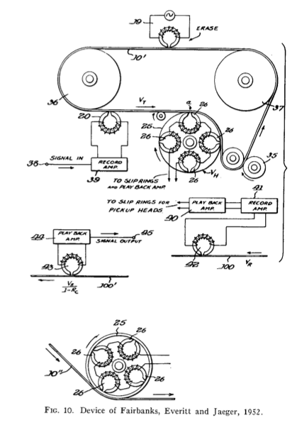
In a 1966 Journal of the Audio Engineering Society article, William Marlens traces the history of analog pitch and time changing devices, with the earliest patents dating back to the 1920’s. The basic idea of all of the patents was to record the audio signal onto some moving medium (tape, wire, film, etc.), and then use a rotating playback head, where the read heads would be moving at a different rate as the recording head:

The rotary playback head has 2, 4 or more read heads. By adjusting the rate of the rotation relative to the tape motion, the pitch of the signal can be raised or lowered. Time expansion / compression can be achieved by speeding up or slowing down the rate of the tape, while keeping the tape heads moving past the tape at a rate that is identical to the original recording rate. As a given tape head comes into contact and is rotated away from the tape, the output signal from that given head will fade in and out, which results in a natural cross-fading of pitch shifted segments.

It is hard to track down audio examples of these early time/pitch changers. Stockhausen made use of one for Hymnen, and other European electronic music studios had similar devices on hand, but the most common use in the US seemed to be shortening audio for commercials to fit a given length. Strangely enough, the Beach Boys seem to have made use of a rotary head pitch shifter on a few songs. Listen to the vocals in “She’s Going Bald” off 1967’s Smiley Smile, starting at 0:51, to hear the characteristic formant shift and warbly sound of a cross-fading pitch shifter.

The Beach Boys also used a fixed rotary speed to add a metallic effect to the drums on “Do It Again.” It is most obvious on the intro:

Wendy Carlos has a detailed blog post about her experiences with the Eltro “Information Rate Changer.” Carlos describes how this 1960’s rotary tape head device was used for the voice of HAL 9000 in “2001” (Carlos wasn’t involved with 2001, but had the story relayed to her by Stanley Kubrick). Apparently the Eltro was used on HAL’s voice throughout the film, but the effect is most obvious in the “death” scene. At 3:06, you can hear the voice start to warble more, presumably as the signal’s pitch was shifted further downwards:

One of Carlos’ experiments involved recording a signal onto an Ampex tape deck, using the Eltro to play back the signal, and sending some of the pitch shifted signal to the record head of the Ampex. This resulted in a pitch shifted tape delay loop, where each repeat was higher (or lower) in pitch. This pitch shifted feedback, in digital form, is a crucial component of the Eno/Lanois shimmer effect. It seems that Wendy Carlos was exploring similar realms a few decades earlier.